
How To Wire a Single-Pole Light Switch?
Single-pole switches are for the lights controlled from one location only, like bedroom ceiling lights or outdoor porch lights. Also known as single-way switches, they can also control electronics, like floor lamps and garbage disposals. This is the most common switch used in the household.
Wiring a single pole switch is a common task that you can do yourself if you follow the right safety precautions and steps. It is not that difficult compared to other types of electrical work.
A single-pole switch looks like two screw terminals along the switch, with each of these terminals connected to the hot wire. The two hot wires are switchable and can be connected to either side.

Modern single-pole switches include a green grounding screw, which must be connected to the grounding system. Older switches might lack this feature, but when upgrading, it's crucial to ground the new switch. The grounding method varies, typically involving a pigtail connection between the switch's grounding screw and the circuit's grounding wires.
Here’s a basic guide on how to wire a single pole switch:
What You’ll Need:
- Single pole switch
- Screwdriver
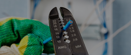
- Wire strippers
- Voltage tester
- Electrical tape
- Wire nuts (if needed)
Preparation:
- Turn Off Power: Before starting any electrical work, ensure the power is off at the breaker box to avoid any electrical shock.
- Test for Power: Use a voltage tester to check the wires you'll be working on to ensure the power is indeed off. Make sure to test all wires in the box, as well as screw terminals.
Wiring Steps:
- Remove the Old Switch (if replacing):
- Remove the faceplate by unscrewing it.
- Unscrew the old switch from the electrical box and pull it out with the wires still attached.
- Use the voltage tester again to check each wire and ensure the power is off once again.
- Prepare the New Switch:
- If the wires are not yet stripped, use wire strippers to expose about 3/4 inch of copper wire on each wire.
- If the wires are poked into the back of the old switch, cut them close to the switch and strip the ends.
- Connect the Wires:
- Attach the black (hot) wire to one of the terminals on the switch. It doesn’t usually matter which terminal on a single pole switch.
- Ensure each hot circuit wire has 1/2 to 3/4 inch of bare wire at the end, formed into a hook-like loop.
- Bend each hot wire end into a C-shaped loop and wrap it around a screw terminal on the switch in a clockwise direction.
- Connect the white (neutral) wire to the other terminal. In a switch loop setup, the white wire is used as a hot wire, especially if marked with black or red tape or paint. Even a switch loop setup can have additional white neutral wires.
- If there is a green or bare copper wire (ground), attach it to the green screw on the switch.
- If there are two grounding wires, attach a grounding pigtail to the switch's grounding screw, then join the pigtail to the circuit grounding wires with a wire connector.
- Pigtailing is also used to connect a metal electrical box to circuit grounding wires. This isn't necessary with a plastic electrical box.
- Secure the Switch:
- Tug on all connections to ensure they are tight.
- Carefully place the wires back into the electrical box.
- Screw the switch into the box, ensuring it’s straight and secure.
- Attach the faceplate.
- Restore Power and Test:
- Turn on the power at the breaker.
- Test the switch by turning it on and off to ensure it’s working correctly.
Does it matter how a single pole switch is wired?
For safety and functionality, it does matter how a single pole switch is wired, even though it does seem like an easy and straightforward electrical job.
Here are the most important considerations when wiring a single pole light switch:
- Typically, a single pole switch has two terminals (excluding the ground terminal). One terminal is for the incoming hot (live) wire, usually black or red. The other terminal connects to the wire, which controls the light fixture or device. In basic wiring setups, neutral wires do not connect to the switch; instead, they pass through the switch box and continue on to the light fixture.
- The switch should interrupt the hot (live) wire rather than the neutral wire. This is important because interrupting the hot wire ensures the circuit is completely off when the switch is turned off, preventing potential electric shock during maintenance or bulb changes.
- If your switch has a grounding screw (usually green), it's important to connect a ground wire (either green or bare copper) to it. This helps to divert any stray current safely to the ground in case of a wiring fault, thereby reducing the risk of shock.
- While the orientation (up for on, down for off) isn't critical to the function of the switch, it is a standard convention that enhances usability and meets common expectations. This orientation can also help in emergency situations when the switch needs to be quickly turned off.
What is the common wire on a single pole switch?
Unlike in three-way or four-way switches, there are no designated common wires in a single-pole switch. There are hot, neutral, and ground wire. It is possible that a hot wire is reffered to as hot, but this is not a common designation.
Two -Wire Setup vs. Three-Wire Setup of a Single-Pole Switch
Single pole switches can be wired in both two-wire and three-wire configurations. These setups refer to how the electrical wiring is arranged between the power source, the switch, and the light fixture or other electrical load.
Two-Wire Setup:
In a two-wire setup, the power supply (hot wire) goes directly to the switch, and the switch is connected to the load (such as a light fixture). This configuration is often referred to as a "switch loop."
- Wiring:
- The switch box's two wires are the hot and load wires.
- The switch opens or closes the circuit, interrupting the flow of power to the load.
- Common Usage:
- This setup is typical when the power source is routed to the switch first.
- When the switch is turned off, the circuit is open, and no power flows to the fixture.
- Grounding:
- Often, the switch box and the light fixture box are grounded separately.
- If a ground wire is present, it should be connected to the switch's ground terminal or left alone if not available.
Three-Wire Setup:
In a three-wire setup, the power is supplied to the light fixture first, and the switch simply interrupts the circuit. This configuration also involves a switch loop but differs in how the wiring is arranged.
- Wiring:
- The power source goes directly to the light fixture.
- The switch box contains three wires: a hot wire, a neutral wire, and a ground wire.
- The hot wire is typically black or red, the neutral wire is white, and the ground wire is green or bare copper.
- The hot wire and the neutral wire are connected to the switch, while the ground wire may or may not be present. If present, it should be connected to the switch's ground terminal.
- Common Usage:
- This setup is often used when the power source is routed to the light fixture first.
- It is common in setups where multiple light fixtures are controlled by the same switch.
- Grounding:
- As with any switch installation, grounding is important for safety.
- The ground wire should be connected to the switch's ground terminal or secured inside the box if not used.
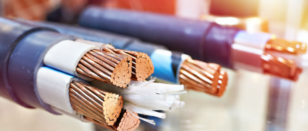
NM-B Romex For Single-Pole Light Switch
The cable typically used for single-pole switch is NM-B Romex for interior indoor wiring.
- For 15-amp breakers, use 14/2 or 14/3 NM-B Romex depending on configuration.
- For 20-amp breakers, use 12/2 or 12/3 NM-B Romex.